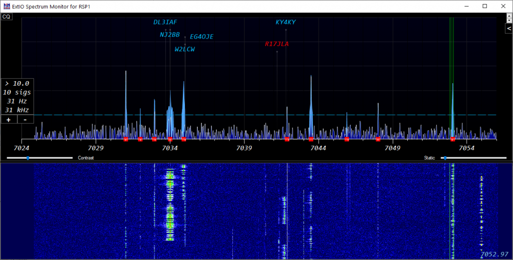
The Spectrum Display Window
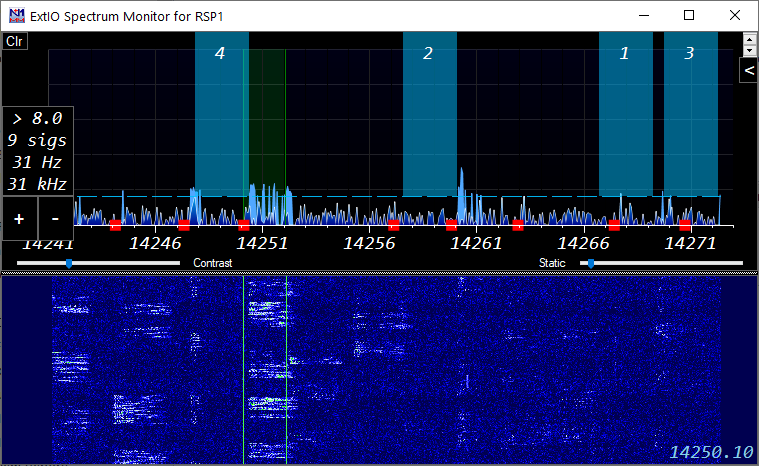
Spectrum Display Window – If your red dots don’t line up with signals, adjust the noise floor. Then use Shift+up/down to jump from signal to signal! If you are having trouble finding a CQ frequency, press the CQ Button!
The Spectrum Display Window can display spectrum data in 6 ways:
- Using a vendor-provided ExtIO dll and N1MM SDR Server
- Via CAT data from radios that support it (newer Icoms)
- Via an ExtIO dll provided by the SDR vendor
- Directly reading IQ data provided by the radio (IC-7610 only)
- Using level data sent from another source (Flex radios, N1MM spectrum windows, Waterfall Bandmap program).
- Via Airspy’s Spyserver program.
What is unique about the N1MM+ Spectrum Window is its ability to identify signals and allow the user to jump to those via keystroke as well as compare them to local and RBN spots to identify unspotted and already worked signals.
Supported Radios & Interfaces
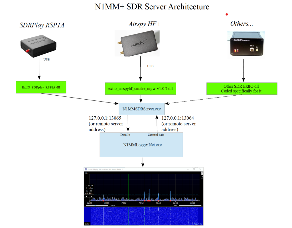
N1MM SDR Server – For radios with Extio dll support – THIS IS THE PREFERRED METHOD FOR SDRPlay and Airspy HF+/Discovery SDRs
- Download the correct ExtIO dll from your SDR vendor’s site and place in the N1MM+ *Program Install* directory. This usually C:\Program Files (x86)\N1MM Logger+. Download:
- Airspy HF+/Discovery: from https://airspy.com/download/
- SDRPlay: from
- SDRPlay Downloads – Select API – Vx.xx (Multiplatform) and install. Note that it reboots without warning as part of “Finish Install”
- Download ExtIO dll
- DO NOT DOWNLOAD THE TCP EXTIO plugin. That is the wrong one.
- Start N1MM+ and open a Spectrum Window.
- Open the Spectrum Dialog (gear icon). Select N1MM SDR Server
- Select the dll and let the source name default to the dll name.
- You can only run one program at a time using the output of an SDR. Don’t try to run SDR# or SDRuno and the N1MM+ spectrum display at the same time.
- SDRPlay Tips:
- Download and install HDSDR.
- Place the ExtIOfor your SDR in the HDSDR program directory.
- Click the SDR Device button in HDSDR
- Change the options below
- Set the IF Mode to Low IF
- Set the IF Bandwidth to its minimum value (usually 200 kHz)
- Adjust the gain control(s) for a reasonable amount of “grass” at the bottom of the spectrum display. You will have to close the SDR UI to see the level. You will likely need to repeat these steps.
- Exit both the SDR ExtIO UI and HDSDR
- In the geari icon settings dialog, set the Freq Bins to 16384. This is a good start at providing high resolution at minimum cpu utilization. You want about 50 Hz/bin as shown in the box that shows resolution, signal count and bandwidth.
- Airspy Tips:
- Close N1MM+
- Start N1MMSDRServer.exe in: “C:\Program Files (x86)\N1MM Logger+\N1MMSDRServer.exe” as ADMINISTRATOR
- Press the start button for the Airspy dll
- Open the SDR UI with the button from the SDR Server application
- Check the title bar of the Airspy SDR UI. If the firmware version number is not the latest available, first upgrade your firmware. You can download the firmware on the Airspy site. The instructions are in the readme.txt file of the download
- Set the sample rate to 192000 (you must be running as ADMIN for this to be saved). This will result in minimum CPU utilization but slower signal response. For faster signal response use the 912000 sample rate. You will need to adjust your Freq bins higher to 64k or so if you choose this value for sample rate.
- Close the SDR UI with the button from the SDR Server application
- Close the SDR Server application
- Open N1MM+
- In the gear icon settings dialog, set the Freq Bins to 8192. This provides high resolution at minimum cpu utilization. You want about 50 Hz/bin as shown in the box that shows resolution, signal count and bandwidth. If it is higher than 23, the sample rate steps above probably failed.
- You may run N1MM SDR Server on a different computer. To do this, change the SDR Server Connection Address to the address of the computer running SDR Server. You will need to start the server manually.
- You can serve more than one N1MM+ SDR display on different computers. Only the first computer will be able to change the SDR frequency.
- N1MM SDR Server supports multiple SDRs, but only with ExtIO dlls that recognize different SDRs. You cannot rename a dll to accomplish this. It is the internals of the dll that recognizes a particular SDR. A workaround to this problem is to run SDR Server on mulitple computers. You’ll need to put the ip address of the 2nd computer in the Connect tab of the associated spectrum display window.
- Airspy server can be used as a way to run a second Airspy on the same computer.
- Always Open/Close the SDR UI by pressing the button in the N1MM SDR Server program. (SDR Server shows in your task bar with a spectrum display icon)
Airspy HF+ Dual Port / Airspy HF+ Discovery
SDR Server is the preferred way to support this device. See the SDR Server section above.
- Download the correct ExtIO dll from https://airspy.com/download/ and place in the N1MM+ *Program Install* directory. This usually C:\Program Files (x86)\N1MM Logger+.
- Start N1MM+ and open a Spectrum Window. Right-click and set the source to “I/Q via ExtIO.dll”
- Select the correct dll in the gear icon settings dialog.
- You can only run one program at a time using the output of an SDR. Don’t try to run SDR# and N1MM+ spectrum at the same time.
- Tips:
- In the gear icon settings dialog, open the SDR UI via the Open button
- Set the sample rate to 192000. If you can’t set this to 192000, you may not be running the latest Airspy firmware.
- Close the SDR UI by pressing the Close button in the gear icon settings dialog.
- Then set the Freq Bins to 8192. This provides high resolution at minimum cpu utilization.
- If you need two Airspy HF+ spectrums, one must be via Spyserver (see next section).
Airspy HF+ via Spyserver (this is distinct from SDR Server above)
No other Airspy models are supported. Can be used with any transceiver.
- Download SDR# software to downloads from https://airspy.com/download/
- Create a new directory SDR# on your C drive (i.e. C:\SDR#) or in your N1MM+ *program* install directory (typically, C:\Program Files (x86)\N1MM Logger+\SDR#).
- Copy all the files from the downloaded SDR# to the new directory. If you want to start the server manually, you can put it wherever you want.
- Important: Change the device_type= in spyserver.config to AirspyHF+
- Important: Change the device_sample_rate = 768000 (Do not use the default)
- Change fft_fps= to 6. This improves cpu consumption
- Start N1MM+ and open a spectrum window
- Right-click and set the Source for the spectrum window to Airspy HF+
- If there are bugs in setup, closing the program and restarting at this point may clear them. I need to fix them, but you probably want to get on with using it at this point.
- There is code included for local Airspy servers to suppress the spectrum & waterfall displays for 200 msec after the associated radio stops transmitting. It will also suppress the display if a very strong signal is present on the transmit frequency.
- To add a second Airspy HF+ you will need to:
- Specify the airspy serial number that you want to serve in spyserver.config. That should show up in the window that runs when you start it.You may have to connect them one at a time to figure this out.
- Change the bind port from 5555 to 5556 (or whatever)and bind to that port in the 2nd spectrum window gear icon settings dialog.
- You will need to start a second copy of spyserver manually with the different ini file.
SDRPlay
SDR Server is the preferred way to support this device. See the SDR Server section above.
- Install SDR Uno to accomplish installation of the device.
- Download the correct ExtIO dll from https://www.sdrplay.com/downloads/ . and place in the N1MM+ *Program Install* directory. This usually C:\Program Files (x86)\N1MM Logger+
- Start N1MM+ and open a Spectrum Window. Right-click and set the source to “I/Q via ExtIO.dll”
- Select the correct dll in the gear icon settings dialog.
- You can only run one program at a time using the output of an SDR. Don’t try to run SDRUno and N1MM+ spectrum at the same time.
- Start N1MM+ in: “C:\Program Files (x86)\N1MM Logger+\N1MM Logger+.exe” as ADMINISTRATOR if you need to change the parameters below.
- SDRPlay Tips:
- Open the SDR UI with the button from the IQ tab.
- Set the IF Mode to Low IF
- Set the IF Bandwidth to its minimum value (usually 200 kHz)
- Adjust the gain control(s) for a reasonable amount of “grass” at the bottom of the spectrum display.
- Close the SDR UI by pressing the button on the IQ tab.
- If you need two SDRPlay spectrums, at least one must be supported via the Waterfall Bandmap program.
IC7610 using native FTDI interface
- Download the correct Icom HDSDR installer. This will install the USB driver. Install it with the radio disconnected.
- Install a second USB cable from the second USB port on the rear of the IC7610 to your computer. Start N1MM+ and open a Spectrum Window.
- Copy FTD3XX.dll and FTD3XX_NET.dll to the PROGRAM install directory (typically, C:\Program Files (x86)\N1MM Logger+)
- Right-click and set the source to “IC7610 I/Q via FTDI.dll”
- Note that the IQ tab dll combox will hide any IC7610 Extio dlls. They are no longer needed. This connection allows choosing of main/sub rx by selecting the Associated radio. The ExtIO.dll version did not.
- The Freq Bins selection will determine the resolution of the display. Higher numbers use more CPU and produce finer resolution. Use the minimum for the lowest resolution you plan to use. 65536 is a good place to start and will give you 30 Hz resolution.
- You may open two instances of the IC7610 I/Q via FTDI.dll with associated radios of 1 & 2. These correspond to main and sub receivers. In order for this to work, you will need Dual Watch to be on. Note that this configuration overloads the radio to the point where the touch screen does not reliably work. Turn off Dual Watch and touchscreen operation will resume. Another way of getting both receivers to display a spectrum is to use the CAT spectrum of the radio on one of the receivers.
Other SDR Radios via SDR Vendor Provided ExtIO*.dll (as SDR adjunct to any transceiver)
- This connection approach is being discontinued on 2024-01-31
- SDR Server is the preferred way to support these devices. See above.
- Download the correct ExtIO dll from the vendor website and place in the N1MM+ *Program Install* directory. This usually C:\Program Files (x86)\N1MM Logger+. (Some radios, like the IC-7610 require addtional files. Read the radio’s documentation for using HDSDR with the radio and emulate the install instructions, but put in the N1MM Logger+ directory.)
- Start N1MM+ and open a Spectrum Window. Right-click and set the source to “I/Q via ExtIO.dll”
- Select the correct dll in the gear icon settings dialog.
- Tested radios include: SDRPlay RSP1, RSP1A, RSP2, RSPDuo, Airspy HF+, Icom IC-7610.
- A link to the Airspy HF+ extio dll can be found in Airspy HF+ page in the “Supported Software” section.
- Be sure to install the driver for the SDR if required. SDRPlay would need you to install SDRUno to install the USB driver.
- You can only run one program at a time using the output of an SDR. Don’t try to run a program like SDRUno and N1MM+ spectrum at the same time.
- Other radios may need the “Reverse I/Q” checkbox checked if the spectrum moves in the wrong direction. Notify the team and we will include the Radio to select I/Q properly. We will need to know the ExtIO*.dll name for your radio.
- I don’t plan to support any other radios at this point. Why? Two reasons. SDRs are very idiosyncratic in how they work. Each seems to have its own set of issues. I don’t have all these radios to debug (and I don’t want to have them). The second reason is that owners usually just say something like “I tried the spectrum window with my Toothgnasher SuperSDR and it doesn’t work. What gives?” There is not a lot to go on to debug that. You might want to report what settings you used, and the actual symptoms.
Icom IC-705, IC-7300, IC-7850/51, IC-7610, IC-9700, IC-7760
- Must use the USB cable virtual COM port for radio control. Unplug the CI-V cable.
- Set Right-Click Radio source to Radio 1 or Radio 2 as appropriate
- Must have the radio menu CI-V USB Port set to Unlink from [Remote}
- Must have the radio and program baud rate set to 115200 baud.
- After the program and the radio is set to 115200 baud, exit the program and restart.
- Note that the preferred method for supporting the IC-7610 is via the native FTDI interface (see above).
Flex 6300/6400/6400M/6500/6600/6600M/6700 Radios
These radios are supported via CAT and UDP – requires SmartSDR V2.0 or later software.
- If a supported Flex radio is detected, N1MM+ will send commands to the radio to start and stop the spectrum. It will send your local IP address and port 13064 to the radio. Note that the program can get confused if there is more than one local IP address in the computer, e.g. a NIC connected directly to the Flex separately from the NIC or WiFi adapter connected to the LAN. Therefore, do not connect your Flex directly to the computer via Ethernet. Connect the Flex to the radio via your router so that the network adapter connected to the LAN is the only one active in the computer.
- The Spectrum Window should automatically find the Flex spectrum feed if it is already sending it. Otherwise, start the Flex and do the following
- Start a new Spectrum window and select “For all other radios, source named…” as the source. The Flex should already be transmitting its identifying information, so when you go to choose the source, pick the source you want from the drop-down list
- Resolution in the N1MM+ spectrum display will be dependent on the zoom level of the Flex panadapter. Bear in mind that the precision of the signal marking is dependent on the zoom level & consequent bin/pixel size. Something between 20 and 50 Hz per pixel would be a good place to start
Elecraft K3/K3S/KX3 plus software/hardware:
- Win4K3Suite ( https://va2fsq.com/ ) software plus hardware as described below:
- K3S, or K3 with KXV3, plus LP-PAN or SoftRock II Lite, plus stereo sound card – connect LP-PAN or SoftRock to IF Out, set right-click spectrum source to “For all other radios, source named “Win4K3Suite”. See Win4K3Suite documentation for Win4K3Suite software setup
- K3S, or K3 with KXV3, plus SDRPlay (RSP1 or RSP2) – connect SDRPlay to IF out, see Win4K3Suite documentation
- KX3 plus stereo sound card – see Win4K3Suite documentation
- KX2 plus SDRPlay (RSP1 or RSP2) plus an external transmit/receive switch – see Win4K3Suite documentation
- Waterfall Bandmap program ( https://groups.io/g/waterfallbandmap ) plus hardware as described below:
- K3S, or K3 with KXV3, plus LP-PAN or SoftRock, plus stereo sound card:
- Connect LP-PAN or SoftRock to IF Out. Put the WB program in Sound Card mode, Offset with LP-PAN is approx. -6000 (varies with mode, roofing filter offset, SHIFT control settings). If traces move the wrong direction in the waterfall when tuning, check (or uncheck) Swap I&Q. Swap I&Q checked/unchecked setting for 6m is opposite to the setting for HF. Set right-click spectrum source to “For all other radios, source named “Waterfall Bandmap”
- K3S, or K3 with KXV3, plus ExtIO-capable SDR (including SDRPlay):
- Put the WB program in ExtIO mode (ExtIO dll must be in the WB program directory)
- RF-based: Connect SDR to a splitter in a jumper between RX Ant Out and RX Ant In – RX Ant must be selected in the K3. Offset zero, SDR at IF check box unchecked . Set right-click spectrum source to “For all other radios, source named “Waterfall Bandmap”
- IF-based: Connect SDR directly to IF Out. Check the SDR at IF check box, set IF to 8215, Offset to zero as a starting point, but offset varies with mode, roofing filter offset, SHIFT control settings. May need to check Swap I&Q if traces move in the wrong direction when tuning – 6m and HF will be opposite settings for this, and offset settings may also differ between 6m and HF. Set right-click spectrum source to “For all other radios, source named “Waterfall Bandmap”
- Put the WB program in ExtIO mode (ExtIO dll must be in the WB program directory)
- KX3 plus stereo sound card:
- Connect KX3’s I/Q output to the sound card. Make sure the box to the right of the Start button reads “Sound card based SDR”. Select the sound card connected to the I/Q output to be the Input device. The offset should be set to zero. If traces move the wrong direction in the waterfall when tuning, check (or uncheck) Swap I&Q . Set right-click spectrum source to “For all other radios, source named “Waterfall Bandmap”
- K3S, or K3 with KXV3, plus LP-PAN or SoftRock, plus stereo sound card:
Elecraft K4 native spectrum:
- Make sure you are running the latest version of the K4 firmware. External spectrum data is not available from earlier versions
- In the Configurer one of the options in the list of ports is TCP. This is used by the K4 to support radio control via TCP (Ethernet). When TCP is selected, enter the IP address and TCP port used by the radio in the box in the IP Addr:Port column. The radio’s IP Address can be found in the K4’s configuration menu under “IP Address”
- You may connect to your K4 using TCP as described above. If you choose to connect to the K4 via a virtual com port, you must include the ip:port in the provided space in the configurer. The spectrum level data is sent on the next higher TCP port and the program will automatically acquire it. The default port for the K4 is 9200. You do not need to enter the K4 spectrum port, just the control port
- To create a spectrum window, open the Spectrum window dialog by using the gear icon in the upper right corner. Choose “External (WB, Flex etc.). Enter/choose the spectrum name for the K4, e.g. “Radio 1 Pan A”. If you are SO2V, you will also see “Radio 1 Pan B”.
- The +/- and center buttons work for this configuration.
- The K4 spectrum is currently only supported as Radio 1
- It would be worthwhile to make the K4’s address a static address in your router so that it does not change over time. Better yet, you can also use the K4’s name, e.g. K4-SN01234. i.e. specify the IP/Port as: “K4-SN01xxx:9200”
For those who own Win4YaesuSuite
In addition to generic SDR solutions, for those who own Win4YaesuSuite (http://yaesu.va2fsq.com/) software, plus hardware as described below:
- LP-PAN plus stereo sound card (FTDX5000 or FTDX3000 only) – connect LP-PAN to IF Out, see Win4YaesuSuite documentation for software setup
- SDRPlay (RSP1 or RSP2) – connect SDRPlay to RX out or IF out (depends on radio model), see Win4YaesuSuite documentation for hardware and software setup
Waterfall Bandmap Software
https://groups.io/g/waterfallbandmap
- SDRPlay, FunCubeProPlus, HackRF, LP-PAN, SDR-IQ, RTLSDR, SoftRock, etc. – SDRs and panadapters that produce I/Q output either via ExtIO.DLL or via a sound card can be used together with almost any transceiver using the Waterfall Bandmap software program
- The SDR may be connected to an antenna, to an RX Ant output on some transceivers, or to an IF output on transceivers that have an IF output. Note that if the SDR is connected directly to an antenna, an external TX/RX switch may be required to protect the SDR against RF from the transmitter.
- Start the Waterfall Bandmap program after starting the N1MM+ program but before starting the N1MM+ Spectrum Display window. Configure Waterfall Bandmap according to the Waterfall Bandmap program documentation.
- The Spectrum Window should automatically find the spectrum feed if Waterfall Bandmap is already sending it. Otherwise, start Waterfall Bandmap and do the following
- Start a new Spectrum window and select “For all other radios, source named…” as the source. Waterfall Bandmap should already be transmitting its identifying information, so when you go to choose the source, pick Waterfall Bandmap from the drop-down list (if the list does not already contain Waterfall Bandmap, type it in)
- If you find “smearing” of the blue spectrum lines while tuning, use the right-click option “Reduce spectrum smearing while tuning” to clear spectrum data each time the frequency is changed. This is needed because the source is getting the radio frequency information after the spectrum window gets it.
- RF or IF > SDR/panadapter > Waterfall Bandmap > N1MM+ Spectrum Window
- SDRPlay
- In Waterfall Bandmap, after choosing the SDRplay ExtIO dll in the text box at the top of the window, select Configure and set the SDRPlay’s IF Mode to Low IF and the IF Bandwidth to 200 kHz. Adjust the LNA & gain controls to limit the amount of noise generated when strong signals are present. The noise will appear as traces in the waterfall, but there are no signals there. The traces will occur coincident with the strong signal transmitting and will occur at various places in the spectrum. The SDRPlay has very high gain to work with short, inefficient antennas, but you don’t need that much gain with a beam or full size dipole.
- Use a USB 3.0 controller for the SDRPlay. If you find that mouse & keyboad operation is affected, you may want to put the mouse & keyboard on the same or different USB 3.0 hub. You will have to experiment. In addition, USB 3.0 devices can emit 2.4 gHz interference which may affect your wireless mouse or keyboard.
- Use the zoom control in Waterfall Bandmap to set the zoom level as shown in the box on the left hand side of the spectrum window to about 40 Hz/pixel or less for CW & RTTY and to about 100 Hz/pixel for SSB. Higher numbers will result in poor signal detection accuracy.
KE9NS PowerSDR
Supports the Spectrum Window as of version 2.8.0.43 (6/29/17)
http://ke9ns.com/flexpage.html
- Start PowerSDR before starting N1MM+
- The Spectrum Window should automatically find the spectrum feed if it is already sending it. Otherwise, start PowerSDR and do the following
- Start a new Spectrum window and select “For all other radios, source named” as the source. The radio should already be transmitting its identifying information, so when you go to choose the source, pick the source you want from the drop-down list
CW Skimmer version 2.0
http://www.dxatlas.com/cwskimmer/
- In CW Skimmer’s Settings window, select the Network tab and check the “Send Spectrum via UDP” box to send spectrum data to the N1MM+ spectrum window. Set the Source Name to “CW Skimmer”, the Destination Address to 127.0.0.1 (unless CW Skimmer and N1MM+ are in different computers), and the Destination Port to 13064.
- In the Spectrum window, select “For all other radios, source named” as the source and pick “CW Skimmer” from the drop-down list (or type it in if it is not already there).
Other vendors TBD
- Start the source before starting the N1MM+ spectrum window
- The Spectrum Window should automatically find the spectrum feed if it is already sending it. Otherwise, do the following
- Start a new Spectrum window and select “For all other radios, source named” as the source. The source should already be transmitting its identifying information, so when you go to choose the source, pick the source you want from the drop-down list
- Users have reported success with these SDRs & their associated Extio dll:
- Hack RF One & ??.dll
- QS1R
Layout
Spectrum Pane
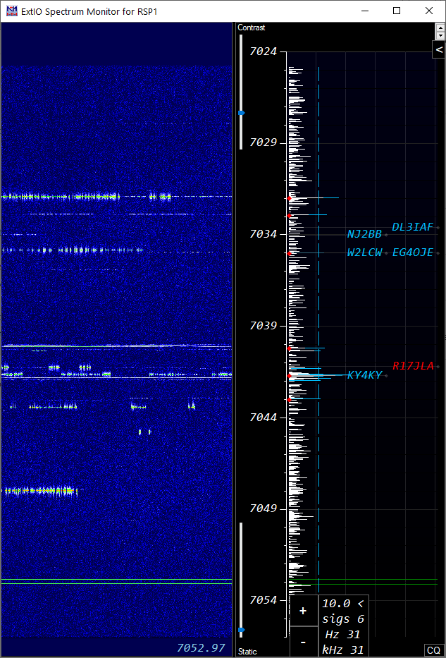
- The spectrum is displayed in the top or right-hand pane, depending on the orientation you choose. Since the option defaults to “Auto” the orientation will change depending on the dimensions of the spectrum window
Waterfall Pane
- The Waterfall pane, when the show waterfall option is selected will appear at the bottom or left of the spectrum pane. Note that in portrait (or bar-chart) mode, the waterfall moves from right to left so that one can see the start and stop of sending and potentially read cw for sources that refresh at a rapid enough rate.
Spectrum Source, Source Options, General Options Panes
Click the gear icon to access
- This dialog is accessed by clicking on the gear icon button at the top right (just below the font sizer arrows) to open or close it
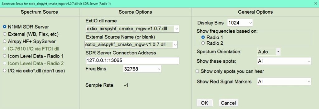
- Spectrum Source Pane
- Choose one of the sources. The requirements for these are described at the beginning of the Spectrum Window help pages.
- Source Options Pane
- This pane shows options relevant to the selection made in the Spectrum Source pane.
- ExtIO.dll name is the name of the hardware vendor provided dll to be loaded by N1MM SDR Server
- External Source Name is the name that N1MM SDR Server or an External source identifies it’s spectrum data with. Once a source starts sending its data, the combo box includes sources that are currently being heard. For N1MM SDR Server, the source name defaults to the extio.dll name.
- SDR Server refers to the local or remote N1MM SDR Server running and serving up spectrum data. The default port for Radio 1 is 13065. The default port for Radio 2 is 13066.
- Note that N1MM SDR Server can be running on a different computer, but must be started manually. If it runs remote you must ensure that the port specified above can send UDP to the server. In addition, you must ensure that the server can send UDP to port 13064 on the receiving N1MM Logger+ computer
- Frequency bins refers to the number of I/Q samples to be processed. The higher the number of samples, the more sensitive the SDR display is and the narrower the range of frequencies displayed. This interacts with your SDRs sample rate.
- Sample rate is the SDR’s reported sample rate
- General Options Pane
- Display bins affects the kHz displayed in the spectrum. More bins use more CPU.
- Choose Radio 1 or Radio 2 depending on which radio (or vfo) you want to control this spectrum
- Spectrum Orientation is best left on Auto. If your spectrum is wider than it is tall, it will display a horizontal spectrum. Otherwise, it will display a vertical spectrum. This option can override that default.
- Show these Spots: Telnet spots and local spots can be displayed on the spectrum display. This combo box allows you to select which categories of spots you want to see.
- Show only spots you can hear: The program tests each spot to see if there is a detected signal, as indicated by red signal markers within the user defined tuning tolerance for the mode. If no signal is found, the spot is suppressed
- Show red signal markers: The program inspects the signal levels shown on the screen and if a signal rises above the mouse-wheel defined signal threshold (blue dashed line) it marks each signal at the bottom of the spectrum display. This control allows you to choose additional criteria for which red makers to show relating whether a signal is unknown (no spots within tuning tolerance), and whether a signal is a mult, Q or non-workable.
- Spectrum Source Pane
Simple Setup Guide for Spectrum Window
General Settings
- Keep noise level low: Adjust the radio’s menu setting (ref level) to keep (“grass” level) low in the spectrum display
- Automatic spectrum scope: For supported Icom and Flex radios, the spectrum scope is turned on startup and turned off on exit
- Opening the first spectrum window: Go to the “Windows: menu in the Entry Window “Windows” to open the Spectrum Window.
- Opening additional windows: Right-click in the Spectrum Window to create additional windows
Controls Overview
- With focus set on the Entry Window, Shift+up moves the frequency to the next signal up in display. Shift+down moves the frequency to the next signal down in the display.
- If you use the spectrum display in the vertical (bar chart) orientation, there is a right-click menu option to change the whether low frequencies display at the top or bottom. The bandmap(s) are changed to match.
- Show signals shows all the signals the window has identified on the frequency axis using your multiplier background color. These signals are also counted in the box that shows the noise floor and pixel width in Hz.
- Shift+up/down *skips* signals that are within tuning tolerance of dupes and non-workables, depending on the options you have chosen in the setup pane.
- Shift+up/down stops at the low and high frequencies in the spectrum. If you are using center mode, the spectrum re-centers on the low or high edge frequencies as appropriate
- Use the up/down keys to fine-tune signals. If the tone is too high, press the down key. Use the up key for signals too low in tone (depends on the sideband in use, i.e. CW-R is opposite to CW).
- Sig (db) is level of signal as shown on the display, relative to ref and includes the preamp level
- Snap to sig – when checked jumps to the nearest signal when you click on the chart. (within 2 kHz). No effect when clicking on the waterfall.
- The noise floor threshold is adjustable with the mouse wheel.
- Signal count is the number of “signals” found above the noise floor reference. Roughly equivalent to how many times your cursor stops traversing the screen. The count includes non-workable spots.
- To mark signals that you don’t want to work, use the Mark button (Alt+M to mark, Alt+D to remove)
- The Static Sensitivity slider should be adjusted until large static crashes light up the “Static Sensitivity” label
- Left single click on the spot label QSYs your Rx & Tx to the frequency of that spot – including split. If you have the noise floor, source level and static sensitivity set properly, you will find that clicking on the spectrum will usually tune the signal more accurately than a cw spot. Note that you must have “snap to signal” turned on for this effect.
- +/- zooms the spectrum in/out. Not all SDR sources support this function. If not supported, the +/- boxes are hidden. These zoom boxes appear under the threshold/sigs/Hz box.
- Alt+Q returns to your CQ frequency. Alt+F8 returns to your last frequency
- The CQ button displays up to five recommended CQ frequencies. These represent the frequencies with least signal content above the signal threshold. This level is computed with a 60 second decay time constant. It changes to Clr after being pressed. If pressed again, the markers disappear. Pressing a function key also removes the markers. While the markers are present the Shift+Up/Down keystrokes jumps from one candidate CQ frequency to another in frequency order. The numbers indicate the rank of the frequencies from 1-5.
- Right-click on the CQ button jumps to the next available CQ frequency above the current frequency.
Mouse (see also the Strange and Mysterious Mouse Wheel, below)
- Left click set sradio receive frequency and snap to closest signal if check box is checked
- Ctl+left click sets split frequency to that frequency. Snap to signal is ignored
The Strange and Mysterious Mouse Wheel
The mouse wheel is used for a number of functions in the Spectrum Window. Lets look at them by pane:
- Spectrum Pane
- When the mouse is over the main portion of the spectrum, the mouse wheel controls the noise floor. You will see the blue dashed line move up and down
- With Icom radios, holding down the Ctl key while moving the mouse wheel in the main portion of the spectrum window controls the REF level of the radio’s spectrum
- With the N1MM SDR Server, Airspy HF+ and SDRPlay, holding down the Ctl key while moving the mouse wheel in the main portion of the spectrum window controls the level of the spectrum. Scrolling all the way down sets the level to Automatic
- With the Airspy HF+, moving the mousewheel when the cursor is over the frequency scale and the Airspy scrolling mode is Fixed, shifts the spectrum frequency
- When the mouse is over the contrast slider, it controls the color of the Waterfall in the pane below. Yeah, I know it belongs in the Waterfall pane, but it flickered badly. You’ll like it better where it is
- When the mouse is over the static sensitivity slider, it controls how much static is detected and discarded. Static does not show in the waterfall
- When the mouse is over the main portion of the spectrum window, Ctrl+Shift+Mouse Wheel controls the dB range displayed.
- When the mouse is over the + or – zoom boxes, the mouse wheel zooms the display to its limits
- Waterfall Pane
- When double vertical bars are displayed, and the mouse is in the Waterfall pane, moving the mouse wheel tunes the radio. Adjust the CW/SSB/Digi tuning values in Configurer/Other tab to your liking and the speed of your radio’s CAT. The frequency as you tune shows in the lower part of the Waterfall. Note that this is the radio reporting back the frequency, so depending on the radio there may be a little lag or a whole lot. If you press Ctl or Shift while turning the mouse wheel, the radio makes larger frequency jumps, just like it does in the Entry Window. The main purpose of this tuning is to allow you to fine tune a signal after clicking on its trace in the Waterfall
The Right-Click Menu
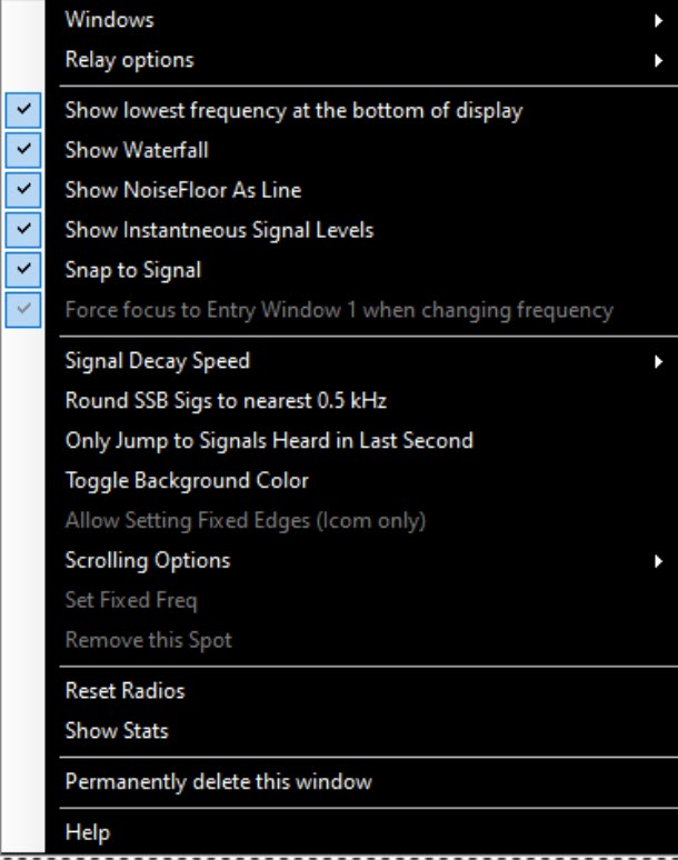
- Right-click opens a context menu
- Windows – lets you choose between spectrum windows that have been configured
- Open a new window – to create a new spectrum window
- Permanently Delete this window – close this window and delete its configuration. It will no longer show in the spectrum window list. For use when you have created multiple spectrum windows
- Spectrum Source – Sources heard by the software will be shown as choices. Until a source name shows up in that drop-down menu, it will not display, or will be greyed out, as it is not bes
- Relay Options – allows you to provide the spectrum displayed in this window to another N1MM Logger+ user.
- Do not relay this spectrum (default)
- Broadcast on IP ports(s)… – Enter list of IP addresses: data is sent to the user specified IP & port. The only port that N1MM+ will listen on is 13064, so only use another port to provide port forwarding with a router at another site
- Name of this source – the name which the other N1MM Logger+ user will use to access this spectrum source
- Reverse frequency scale in bar chart mode – if you check this option, the low frequency of the spectrum will be at the top, matching the way the band map is oriented
- Show Waterfall – controls whether the waterfall is displayed. When the waterfall is displayed the current radio frequency will appear in the waterfall pane. When it is not displayed, the current frequency appears in the spectrum pane
- Show Noise Floor as Line – This is effective only in column (landscape) chart mode. Instead of columns, the instantaneous signal values will be shown as a line and the (decaying) average values that exceed the noise floor will show as a filled line series
- Snap to Signal – When on, clicking on the spectrum will jump to the nearest signal center rather than to the precise point which you click. It will look +/- 2 kHz for a signal
- Show Stats – shows information that the window has collection about the currently displayed spectrum. It will remain for 25 seconds, or click on the X to hide it
- Signal Decay Speed – Controls how fast the blue signal indicator lines decay. For SSB, if you set the signal decay speed to fast, it will find signals more accurately, but skip signals not transmitting at that instant. Use fast for SSB and crowded conditions, slow for quiet bands.
- Round SSB Sigs to nearest 0.5 kHz – experimental option to help with regular dxing. This is not expected to be useful in a contest. Non-sticky to prevent its inadvertent use during a contest
- Only Jump to Signals Heard in the Last Second – Shift+up/down will ignore any signals that are not currently transmitting (experimental)
- Toggle Background Color – to toggle to higher contrast backgrounds – both white & black. Black background is the most readable.
- Allow Setting Fixed Edges (Icom only) – If the spectrum source is an Icom radio, you can force the displayed spectrum not to extend outside of the amateur band. Greyed out for other spectrum sources
- Scrolling Options – Not available for all spectrum sources; greyed out when not available. For other sources, bandwidth and scrolling options are controlled by the spectrum data source (for example, by the application program that is providing the spectrum data to N1MM+). When this option is available, it offers four submenu choices:
- Center Mode – Centers the spectrum display on the current frequency, i.e. the spectrum bandpass moves as the frequency is changed. The center button is hidden in this mode.
- Fixed Mode (with scrolling) – The spectrum display range stays fixed, centered on the initial frequency, except that if the frequency is moved outside the currently displayed bandpass, the center jumps by an amount equal to the displayed bandwidth so that the current frequency is inside the displayed bandpass.
- Fixed Mode – The spectrum display range stays fixed and does not move when the frequency is changed. Set the frequency with the center button or the “Set fixed frequency” right click menu. (See below.)
- Respect Mode Subbands – Restricts the display to show only the subband for the current mode (from the Bandmap window settings)
- Set fixed frequency – Allows you to set the frequency for “Fixed mode above”. This is useful for monitoring a band that you are not yet operating on.
- Show Instantaneous Signal Levels – Hides/shows the noise that does not peak above the signal threshold (blue dashed) line. Makes the display less distracting.
- Remove this spot – does what it says, but is only enabled when you hover over a spot in the spectrum panel of the window.
- Reset Radios – Sends the commands to reinitialize the radios connected to the program (similar to the same option in the Bandmap window). This will often restart the spectrum display on a supported radio.
- Help – link to this documentation
- Windows – lets you choose between spectrum windows that have been configured
Colors
- White is the instantaneous signal level as shown in white on the radio (black on light color skins)
- Blue is a “decaying” representation of the signal *similar* to that on the radio
- The green line is the current Rx frequency
- The horizontal blue line is a measure of the noise floor above which signals are found
- The vertical red line, if shown, is the tx frequency when split
Operation
* Adjust the REF level on your radio (or equivalent in your source) and the mouse-wheel noise floor to the point where the number of signals counted drops suddenly from a high number to a reasonable one. The noise floor is adjustable in 0.2 dB steps from 0-1 dB and in 1 dB steps thereafter. Check that you don’t have the noise floor too high by tuning for a weak signal
- Use the mouse wheel in the chart area to adjust the noise floor. You will see the number of sigs change as you scroll the blue line. If a blue or white signal is above the floor, Shift-up/down will jump to that signal. The noise floor value and # of signals detected are shown in the box near the dB scale.
- Also shown in the little noise floor/signal box is the number of Hz represented by one pixel of incoming data. Note that to see all the incoming pixels, you need to make the graph area of the spectrum window greater than the number of pixels. The number of Hz per pixel affects how many signals can be found. If you have a source generating pixels greater than 100 Hz apart you may lose the ability of the program to find some signals as they are not represented in the source data stream. The size of the spectrum window does NOT affect the finding of signals. That is always done with the incoming source data, not the data as displayed
- If you are short on screen space, Ctl-up/down does not need the old bandmap to be open to work. You can use this one instead
- Turn off “snap to spot” if you find it is interfering with you clicking on signals. You don’t need it if you are zoomed way in as you would often be in center mode
- For DX split operation, use Ctl+click to set the Tx frequency to the point where you think the dx op will answer the next caller. That might be the frequency of the last station that worked him or it might be higher or lower
- Pro Tip: Try setting your up/down tuning increments in Config/Config Ports…/Other to match your preferred zoom level for your spectrum as seen in the left-hand box in the spectrum display. For example, if you like CW resolution at 42 Hz/pixel choose .021 as your up/down increment. For SSB and 105 Hz/pixel, you might choose .0525 as your increment. By choosing multiples, you will minimize jitter in the waterfall display that results from imprecise changes in tuning. Doing this only helps when using the up/down keys to tune or the mouse wheel equivalent.
Relaying and Port Forwarding
The Spectrum Display window can forward the data it receives to another spectrum display window. The other spectrum window can be running in the original instance of N1MM+ or in N1MM+ running on any computer that is reachable via UDP packets. The forwarding computer only sends its spectrum display data: band, frequency, signal strength, display name, scaling factor. The destination instance of N1MM+ is responsible for display settings, the noise floor, and capturing packet spots.
Step 1. Preparing the source instance of N1MM+ to forward its Spectrum Display window
- Using your mouse, right-click in the Spectrum Display window to be forwarded
- From the right-click menu, select > Relay options > Name of this source
- Enter a unique name for this Spectrum Display window. For example, “20M Radio”
Step 2. Preparing and launching the destination Spectrum Display window
Choose one (or more!) of the following options
- Option1. Local Forwarding to a second Spectrum Display in the same instance of N1MM+ (you have only one computer)
- Using your mouse, right-click in the Spectrum Display window to be forwarded (the source window)
- From the right-click menu, select > Relay options > Broadcast on IP/port(s)
- Enter an IP address of 127.0.0.1
- To open the second spectrum display, right-click in the source spectrum display
- From the right-click menu, select > Windows > Open a new window
- In that new window, right-click and select > Spectrum Source > Source named
- Choose the source name that you assigned in the first step of this process. In our example “20M Radio”
- Option 2. Forward a spectrum to another computer on the same LAN (you have more than one computer)
- Using your mouse, right-click in the Spectrum Display window to be forwarded (the source window)
- From the right-click menu, select > Relay options > Broadcast on IP/port(s)
- Enter the IP address of the destination computer. For example 192.168.1.123. You can run IPCONFIG in a cmd window to determine the destination computer’s IP address
- If N1MM+ is already running on the destination computer, close and re-launch N1MM+
- To open a spectrum display window on the destination computer, from the drop-down N1MM+ menu on the destination computer select > Window > Spectrum Display
- In the destination computer’s spectrum display, right-click and select > Spectrum Source > Source named
- Choose the source name that you assigned in the first step of this process. In our example “20M Radio”
- Option 3. Forwarding to remote instance of N1MM+ (you have more than one site)
- Using your mouse, right-click in the Spectrum Display window to be forwarded (the source window)
- From the right-click menu, select > Relay options > Broadcast on IP/port(s)
- Enter the IP address of the remote destination computer. For example 71.233.1.123. From a browser on the remote destination computer, entering “my ip address” will tell you your external IP address
- Set up port forwarding on the router of the remote computer LAN to route incoming port 13064 to 13064 on the destination computer
- If N1MM+ is already running on the remote destination computer, close and re-launch N1MM+
- To open a spectrum display window on the remote destination computer, from the N1MM+ drop-down menu on the destination computer select > Window > Spectrum Display
- In the remote destination computer’s spectrum display, right-click and select > Spectrum Source > Source named
- Choose the source name that you assigned in the first step of this process. In our example “20M Radio”
- Option 4. Forwarding to 2nd remote instance of N1MM+ (you have more than one computer at a remote site)
- Using your mouse, right-click in the Spectrum Display window to be forwarded (the source window)
- From the right-click menu, select > Relay options > Broadcast on IP/port(s)
- Enter the IP address of the second destination computer and specify a different port. For example 71.233.1.321:13900. (cannot be any port currently in use)
- Set up port forwarding on the router of the remote computer LAN to route that new incoming port to port 13064 on the second destination computer
- If N1MM+ is already running on the second destination computer, close and re-launch N1MM+
- To open a spectrum display window on the second destination computer, from the N1MM+ drop-down menu on the destination computer select > Window > Spectrum Display
- In the second destination computer’s spectrum display, right-click and select > Spectrum Source > Source named
- Choose the source name that you assigned in the first step of this process. In our example “20M Radio”
Note that Broadcast on IP/Port can be a comma separated list of IP addresses. For example: 192.168.1.1,79.235.146.132:13064,29.235.146.132:13900 (separate with a comma, but no spaces)
If you want one instance of N1MM+ (e.g. a “slave” instance on a computer that is the source for spectrum data but that is not directly controlling the transceiver) to follow another N1MM+ instance’s frequency & mode (the “master” instance that is interfaced to the transceiver), you can forward the master instance’s broadcast data (in the Configurer broadcast tab) to the slave computer’s IP address, port 13064. You will have to open this port on the destination computer’s network router if the destination is at a remote site or just using a different router.
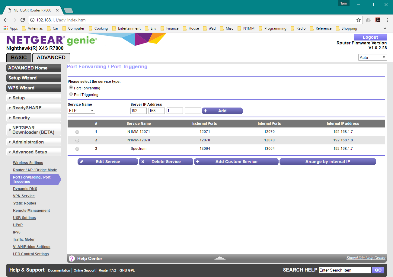
Netgear Routing Example
In the example above, external port 13064 is being routed to port 13064 on the computer with IP address 192.168.1.7 on the LAN. (Line 3 “Spectrum”). This menu is accessed from Netgear’s Advanced/Advanced Setup/Port Forwarding & Port Triggering selection.
Notes
- With most SDRs, if you feed a narrower bandwidth slice to the spectrum display, less noise will be sent as well. Try to use wide bandwidths only on quiet bands where you want to scan the whole band for new signals
- Gaps will appear at the beginning and end of the center mode spectrum display if you are not currently tuned to a whole kHz frequency. This is normal
- If your radio is turned off or not configured properly, you may need to close the spectrum display or perhaps close the program and reopen to get the display to work
- We are focusing on CW and RTTY operation. You can play with other modes, but bear in mind little work has been put into making the window play nice with them
- In SO2V only, the second VFO will be shown with a line in your skin’s highlight color
- Use Fast signal decay for SSB signal detection. Slow signal decay can be used with CW & RTTY to keep signals on the screen longer.
- If you detest the tool tips, you can turn them off at the bottom of Config/Manage Skins, Colors and Fonts
SDR Block Diagram
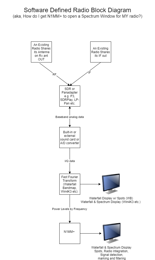
This picture represents non-I/Q support.
For I/Q supported radios (SDRPlay, Airspy HF+ via ExtIO, IC7610 via FTDI), the FFT occurs within N1MM+.
SDR Block Diagram in SO2R Station
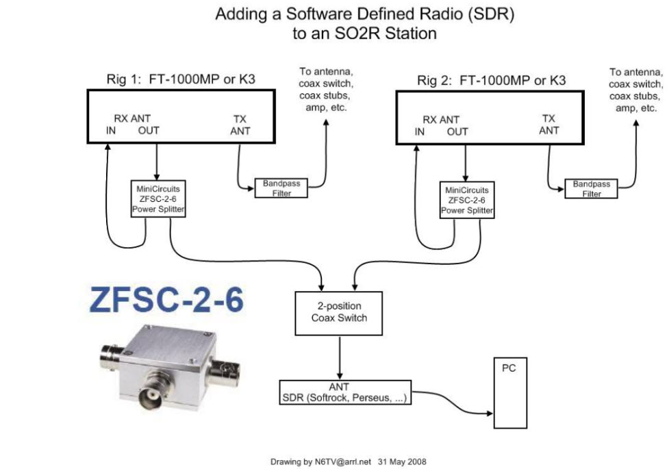
(Thanks to N6TV for the use of his diagram.)
Note: You need to set both radios to listen on the Rx antenna in order for the SDR to receive signals from the transmit antenna during receive. Rx in is where you normally put a receive antenna input. Rx out is connected to the transmit antenna when the radio is receiving.
If you want to allow for a receive antenna in the above configuration, connect the common port of a two position coax switch to the common port of the power splitter. Connect one of the switched ports to Rx Out and one to the receive antenna.