Interfacing Basics
Operating without an Interface – Manual Mode
There are many reasons why you could find yourself operating in manual mode. Maybe you’re just getting started and have not had time to install and configure an interface? Perhaps your radio does not support PC integration, or you have a computer but it lacks the necessary I/O ports to connect a radio? Or maybe you’re operating from a short-term portable location and don’t have the time or equipment to connect the radio to the computer? Whatever the reason, there are special keystrokes that you need to enter in the Entry Window to inform N1MM Loggger+ of the band and mode that you are operating.
Set your frequency by typing it into the Callsign textbox and hitting Enter. If you want the log to only indicate the band, and not specific frequency information, enter the frequency of the bottom of the band in kHz (note that some contest administrators request that manual frequency entries always be bottom of band). If you want the log to include the actual frequency, enter the complete frequency in kHz. For example 14025.1 (or 14025,1 if your computer uses comma as the decimal separator). The new frequency will appear in the title bar of the Entry window.
Enter mode changes similarly. Recognized entries are CW, RTTY, PSK and SSB, USB or LSB. If you enter SSB, the program will substitute the customary sideband (e.g., LSB on 40-160) USB and LSB can be used to enter the opposite sideband, should you ever need to. The mode to be recorded in the log is displayed in the title bar of the Entry window.
For more details about these commands, see the Entry Window Text Commands in the manual.
Basic Radio Control Interfacing
Regardless of whether you want to operate phone, CW or digital modes, the most useful and important interface is the one between your computer, N1MM Logger+ and your radio. Fortunately, virtually all modern radios incorporate a serial port to enable them to swap information and commands with the computer.
A first step is to look up your transceiver in the manual section titled Supported Radios. Assuming you find your radio there, look for any specific settings or peculiarities that need to be addressed and make a note of them.
USB has largely both RS-232 serial ports and LPT parallel ports. If your radio has a standard RS-232 serial port, once you have purchased a USB-to-serial adapter and installed the drivers for it, N1MM logger can work with your radio just fine. If your radio uses either Icom’s CI-V standard or another non-RS-232 serial port, you’ll need an appropriate converter cable to get from either USB or RS-232 to your radio.
Some USB adapters, particularly those using a Prolific chip-set, are erratic with some programs, particularly programs written in Visual Basic (like N1MM Logger Classic). If you encounter quirky performance or an 8020 error, that may be why. See USB Interface Devices for a full rundown on user experience with various specific adapters.
Many radios now have USB ports. If yours is one of these, check the Supported Radios entry for your radio (and the radio manual) to find USB interfacing details.
See this earlier section for information on avoiding problems with USB ports going to sleep.
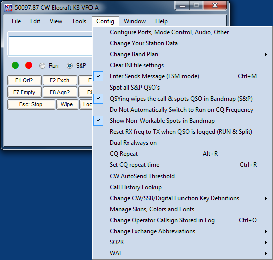
Once you have the hardware hooked up between your computer and your radio, start N1MM Logger+ and open the Config menu in the Entry window. Choose Configure Ports, Mode Control, Audio, Other. Ignore all the other stuff for now.
That brings up the following, rather intimidating dialog. Don’t worry, we’ll walk you through the part you need now.
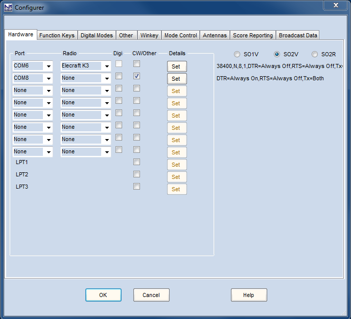
You may want to select SO1V if this is your first experience with N1MM. SO1V allows N1MM to control VFO A in your transceiver. If you are an experienced contester and understand how to operate in split mode (for example, working DX on 40 meter sideband), and especially if you have a radio with dual receivers, you may want to select SO2V. It allows N1MM to simultaneously control both VFO A and VFO B in your transceiver. If you are an advanced contester, whose station is configured with TWO transceivers (one for running contacts and the other for searching for new multipliers), then you will want to select SO2R.One of the advances in N1MM+ is that you can use any COM port numbered 1-99. Click the drop-down arrow to the right of the Port column, and you will see all the serial ports, hardware or USB/virtual, that are active on your PC. Select the one that is connected to your radio. Now click the drop-down arrow to the right of the Radio column, and select your specific radio model. Virtually all Kenwood models use the one common radio configuration, while Yaesu and Icom radios are generally designated by the specific model number – refer to the manual under supported radios for more information. Icom radios also require a Radio Address (Hex Code) – that’s in the same place.
Now click the “Set” button next to the port you have chosen.
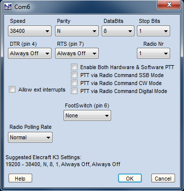
That will bring up this dialog, with connection details. Normally, N1MM Logger chooses the parameters in the first two rows for you, and does a good job. You might want to verify them with your radio manual, just in case. Radio/VFO number should be 1, so that your main VFO will be displayed in the main (first) entry window. The rest of the stuff on this dialog is not important right now, so just click OK to get back to the previous dialog, and then OK again to return to the Entry Window.
If all is well (you did turn your radio on, right?), when that big multi-tabbed dialog closes and the Entry Window reappears, the title bar of the Entry Window will display the radio’s frequency and mode. It’s magic. The “+0.00” simply means that RIT is turned on, but set to zero (no offset)
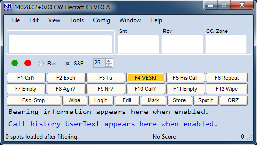
Now that you have radio control, you can do a lot of neat things, but one of the most basic is that you will never again have to worry about accidentally logging QSOs on the wrong band or mode.
Interfacing for Phone, CW and PTT
Of course, controlling your radio through a serial port isn’t the only way to interface N1MM Logger+ and your radio – in fact, long before there were computer-controllable radios, the pioneering logging software authors developed several standards for CW and PTT interfacing, using either serial or LPT (printer) ports.
We’ll start, though, with a discussion of phone interfacing, on the theory that this will be of most interest to new users. Once you’re interfaced, you will be able to store voice messages and play them back through your radio, to save your voice during phone contests.
Phone Interfacing
This topic is covered in introductory form here, and in more detail in two parts of the manual. This rather awkward organization is necessary because N1MM Logger+ is transitioning from Classic’s audio function setup, on the Audio tab of the Configurer, to a new improved option currently on the Config menu, Logger+ Audio.
The Audio tab version works with all versions of the Windows operating system from Windows XP forward. Logger+ Audio works with Windows Vista and thereafter. If you check Logger+ Audio on the Config menu, and you are running an operating system after XP, the Audio tab on the Configurer will not be visible. If you are running Windows XP, the Config menu option is disabled.
Interface Hardware
Of course, you can always use one of the many commercial audio interfaces designed primarily for digital modes. However, if you have a sound card that permits feeding microphone input through it to the line output (most do), and has a mixer that will allow you to independently set the level of the microphone, .wav playback and internally-generated audio (such as for AFSK), you really don’t need an interface at all. On SSB, simply plug your microphone into the sound card mike input. Cable the sound card’s Line Out to the Line In or Phone Patch input of your transceiver, and you’re done.
You may encounter hum, resulting from difference in AC potential between the chassis of your computer and that of your transceiver. In that case, a 600-ohm isolation transformer in the cable between sound card and transceiver is a likely cure. Another approach is to bond the transceiver and computer chassis together with a heavy wire. Many people do both.
If you absolutely must feed the audio output of your sound card into the microphone jack of your transceiver, the level will be far too high. In that case, a simple 10:1 resistive voltage divider is the solution, placed in the audio cable before the microphone jack.
Trouble-shooting phone interfacing
The following discussion is cribbed almost verbatim from audio trouble-shooting notes by David Robbins, K1TTT. If any mistakes have crept in, blame the manual team, not him. It assumes that you’re running Windows XP, using the Configurer’s Audio tab, and all the screenshots below are from that version.
To begin with, make sure you close Windows Media Player, RealPlayer, Audacity, or any other sound playback/recording program you may have open. Start N1MM Logger. On the Config menu, open “Configure Ports, Mode Control, Audio, Other”, also known as the Configurer.
Now select the Audio tab:
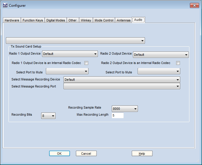
Select option 1 “Only use Radio 1 Output Device. Output on both channels.”
Choosing from the drop-down list at the upper left in “Tx Sound Card Setup”, make sure that the Radio 1 Output Device is correct for your sound card. Typically, the name will appear as “Speakers” with the name of the associated sound device in parentheses. You can select Default as your Output Device, if you have set it as that in Windows, but depending on your version of Windows that may prevent you from muting your microphone while stored voice messages are playing.
If you make an explicit choice of Output Device, you’ll be presented with options under Select Port to Mute. Select Microphone. Then make sure that the Message Recording Device (sound card) is correct (typically the same as your Output Device), and that the Message Recording Port is set to Microphone. Make sure the Recording Sample Rate and the Recording Bits numbers are set to values supported by your sound card.
Now OK out to save these settings, and close N1MM Logger. It’s time to test.
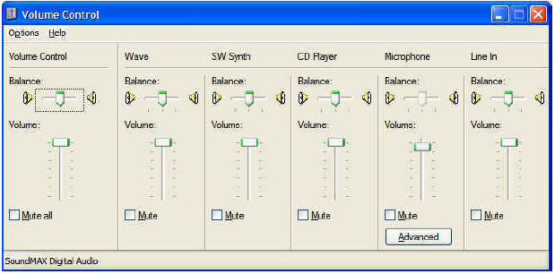
Plug your microphone directly into the microphone jack on your sound card. Plug your headset directly into its speaker output. Open the Windows Volume Control. It should come up with a set of sliders. In Windows XP, they look like this:
Or this, in Windows 7, after you finally drill down through the options on the Control Panel, under Sound”:
Unfortunately, sound card manufacturers have added a dazzling number of bells and whistles the past few years, including software-configurable input and output ports and other gadgets that affect recording. We have to leave you a little on your own here. The important thing is to find the microphone recording volume control, make sure it is selected, and that the level is about 50 percent.
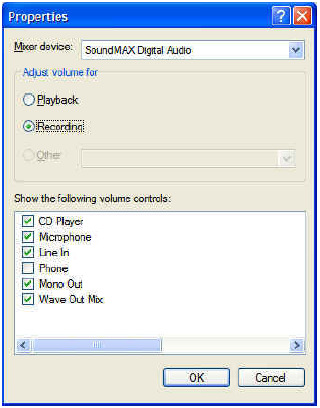
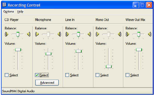
In Windows XP, you may have to go into Options>Properties to check the box to let you see the microphone volume control and those for other sound sources. Under Options>Properties, click the ‘Recording’ radio button, and make sure the microphone is checked on the list of controls:
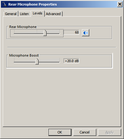
In Windows XP, make sure the Microphone slider is at mid-range and that there is a check in the Select box. If you are using a typical ham microphone, such as a Heil, and you have the “Advanced” button, click on it and select Mic Boost if that option is available, because it provides a 20-30 dB preamp. Now OK out.
Now, when you talk in the microphone, you should be able to hear yourself in the headset. If you can’t, then something is wrong with your settings, hardware or drivers. Try playing existing .wav files using the Windows Control Panel’s Sounds option. Recheck volume and mute settings, check that the microphone is plugged into the right jack, try a different microphone, try a different headset. DO NOT PASS THIS POINT UNTIL YOU CAN HEAR YOURSELF!
Now open Windows Sound Recorder, which is usually found in the Accessories category in your program list. DO NOT open Audacity, any of the audio tools that came with your sound card, or your other favorite tool. Some of them play with the mixer settings and we don’t want that now that they are set. These are for QWindows XP and Windows 7, respectively.
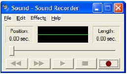
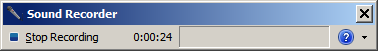
Click the Record or Start Recording button in Sound Recorder, and speak a few words into the microphone. You should see the level indicator deflect in time with your voice. Now press Stop. Press the Play button and you should hear what you just said. If you don’t there is something wrong with your hardware or drivers. Check recording control settings, adjust volume, make sure the microphone is selected as the recording source, and get that 8 year old back to help again! DO NOT PASS THIS POINT UNTIL YOU CAN RECORD AND PLAY. If Windows Sound Recorder doesn’t work, then N1MM likely won’t work and since N1MM is much more complicated it is harder to troubleshoot.
If it’s working OK, now close the Sound Recorder and start N1MM Logger. Put the program in Run mode (Alt+U or click in the Running box) and your radio on USB or LSB, and make sure that the Entry Window’s title bar specifies either USB or LSB (if you don’t have a radio connected, type the appropriate mode in the callsign box and hit [Enter]).
Right-click on any of the message buttons in the entry window. That will bring up the Function Key message editor:
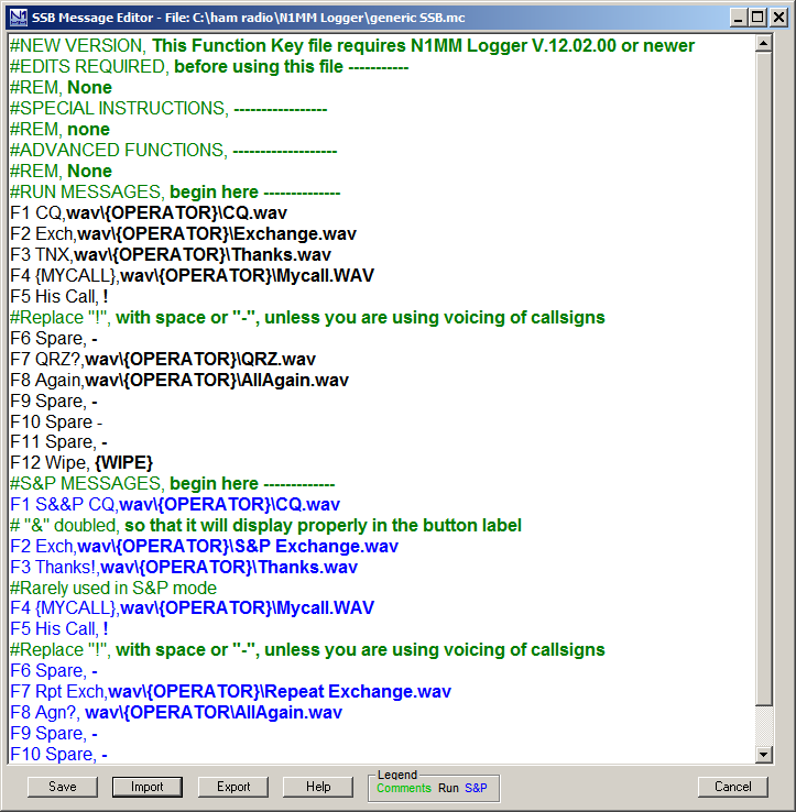
Don’t be intimidated – we’re just going to use this screen to set up a single function key to send a single message, so we can check out the entire flow from pressing a Function Key to having an audio message properly sent to your radio. The filenames and remarks you see in the editor now are the default filenames that are put into the table when you first install MM. If this is not your first time using N1MM Logger, these may not be the first ones you see. For the full story on the message editor, see this page in the manual.
For test purposes, we are just going to use one message, in the slot for Run F1. This is the message that will be sent when the program is in Run mode and F1 is pressed. This is intended to be the location for your CQ Message. If the editor shows “F1 CQ,CQ.wav” in the first row of the Run Messages section, then you’re ready to go. Just close the window with the X in its upper right.
XXXX
There is a critical difference between the “Save” and “Export” buttons in the bottom frame of the Function Key Message Editor. If you click “Save”, the currently-displayed contents (including any changes you have made) are saved in your current database, for use the next time you press a function key. They are also written to the file-name shown in the upper frame of the editor. To save a change on the fly and get back quickly to using the program, all you need to do is click Save and then X in the upper corner to leave the editor and return to the Entry Window. However, if you want to retain the file that was loaded into the editor in its original form – as you might want to with the default files, for example – then you must first click Export, select a filename in the Save Macros to File dialog that opens, and then click Save. Then, you must click Save in the Function Key message editor to load the edited function keys into the current database.
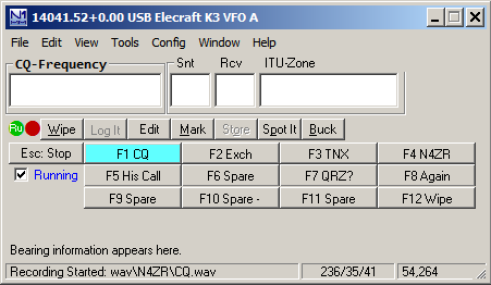
Now, make sure you are in Run mode – that is, that the Run checkbox in the Entry Window is checked. Now watch the bottom line of the Entry Window (called the Status Line) and press Ctrl+Shift+F1. You should see:

One important thing to note here. If you have not entered your callsign under change Station Data on the Config menu, you will not see your callsign in the status line. This is important – stop, go do that, and then repeat this step.
If you speak into the microphone at this point, whatever you say will be recorded in the file CQ.WAV under WAV\your_callsign… Press Ctrl+Shift+F1 again (or ESC) to stop the recording, and look for this report in the same place:
Now press F1. You should hear what you just recorded in the speaker. If you don’t, make sure you’re still in Run mode and look for an error message in the Status Line. We suggest using the Ctrl+Shift+Fx process to record within N1MM Logger, at least until you get truly comfortable with audio files, because a lot of the problems people run into are a result of recording with diofferent programs, or in filenames that are different than the program expects to see.
Now that you’ve got things working, you need to program at least the first few function keys. It’s best to follow the order in the example above, at least for F1-F8, because a little later, when we talk about ESM (Enter Sends Messages) mode, the order is important. Be sure that each Function Key message line begins with the Function Key number, a brief label (like CQ), a comma, and the content of the message
OK, so now you have everything you need to play “canned” audio messages on the air. If you’re content to use VOX to switch your transmitter, and you’re not interested in CW, then you can stop here, for now.
CW Keying and PTT Control
N1MM Logger+ supports several methods of CW keying, but two are not supported. The first of these unsupported methods is CW by audio tone, or MCW, as is done by software such as FLDIGI. The reason for this is that if it is not set up carefully, this method can produce unnecessarily wide signals, or even in some cases two closely-spaced signals from one transmitter.
The second unsupported method involves sending ASCII characters to the radio, which then converts them to CW. Only a few radios have this capability, and in most or all of these the resulting CW operation is far less suited to contest use than the Logger’s own. N1MM Logger+ does not support this method directly, although it is possible for users to use this capability by means of radio control macro commands incorporated into function key messages, provided they are willing to accept some loss of functionality as compared with the directly supported methods.
A full discussion of interfacing is in the Interfacing section of the manual.
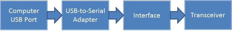
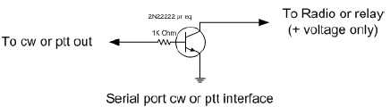
In its simplest form, CW is sent and PTT is controlled by switching lines on a COM or LPT port. This technique allows the simplest possible interface, but one is required. Here’s a block diagram of the COM port setup. For LPT port keying, a USB adapter will not work. Your computer must have a hardware LPT port:
Please note that only a very few radios permit CW and PTT via their built-in serial ports. The rest require that the interface be plugged into the CW key jack on the transceiver. The exceptions to this are covered under Supported Radios.
The interface can be anything from the simplest – one resistor and one transistor – to one of the many units on the market that handle both CW and various digital modes.
Let’s assume you’re going to use this method to start with. Begin by opening the Config menu to the Ports, other dialog:
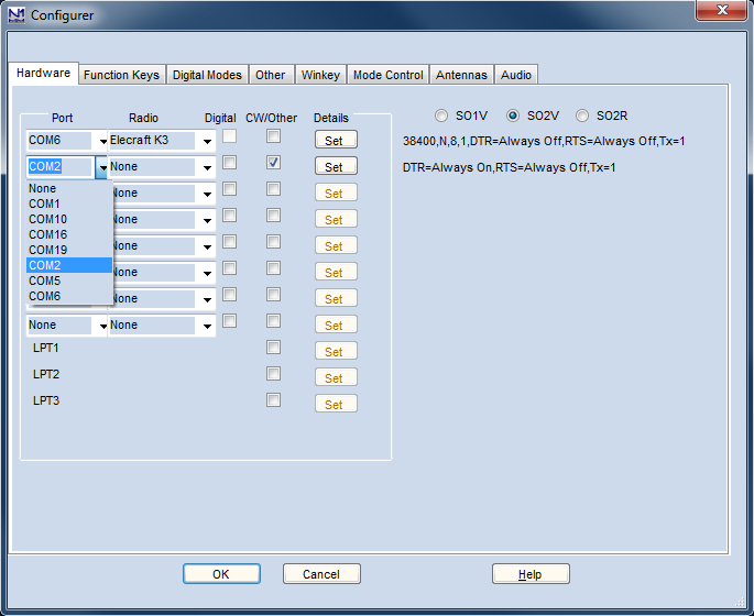
For this example, our CW port will be on the second port we configure (the first port, COM6, will be used for radio control). let’s choose COM2 as our CW/PTT port. After selecting COM2 from the pull-down list of available ports, put a check in the CW/Other box and you’ll notice that the Set button is no longer greyed. Click on it, and open the dialog for that port:
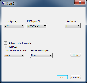
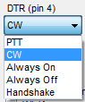
You can configure the DTR pin as either CW or PTT. Click the down arrow and you’ll see the list of possibilities:
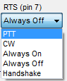
Highlight the one you want, depending on your interface. Now do the same with the RTS pin:
You can use either signal line (DTR or RTS) for either function (CW or PTT); just make sure your choice matches up with the way the hardware is wired up.
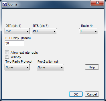
Set the Radio Nr to 1. The PTT Delay setting is to protect the relays in an amplifier by making sure that the T/R relay is closed before the program starts sending CW. The default value of 30 ms. is fine even if you don’t have an amplifier.
OK, now to interface to the rig. The very simplest interface imaginable will work just fine for either the CW or PTT functions with any modern radio; again, there are many commercial options, but here’s the Radio Shack parts solution:
K1EL’s Winkey/Winkeyer devices have become very popular with N1MM Logger+ users. The chips are built into a number of interfaces. The stand-alone Winkeyer USB will key two radios and provide PTT functions for both on all bands, simplifying changing modes considerably.
Follow the instructions that come with your interface in setting up CW keying. For the stand-alone unit, You’ll need to determine which port your Winkeyer is listening on, and then check its CW/Other box. Finally, click the Set button and check the Winkey box. That’s all there is to it. Do NOT try to configure DTR or RTS for a Winkeyer; checking the Winkey check box automatically sets these to the correct settings for the Winkeyer.
You will probably also need to review (and likely change) settings on the Winkey tab of N1MM Logger+’s Configurer (Config>Ports, Other). One important one with many transceivers is the Lead Time parameter, needed to prevent Winkey from starting to send CW before your transceiver is ready to make RF. A setting of 2 (20 mS.) is usually plenty; more can make manual keying difficult.